
L322 Range Rover System Description and Operation
TRANSFER BOX
DESCRIPTION AND OPERATION
41-19
Diagnostics
The transfer box ECU can store fault codes which can be retrieved using TestBook/T4 or a diagnostic tool using
KW2000* protocol.
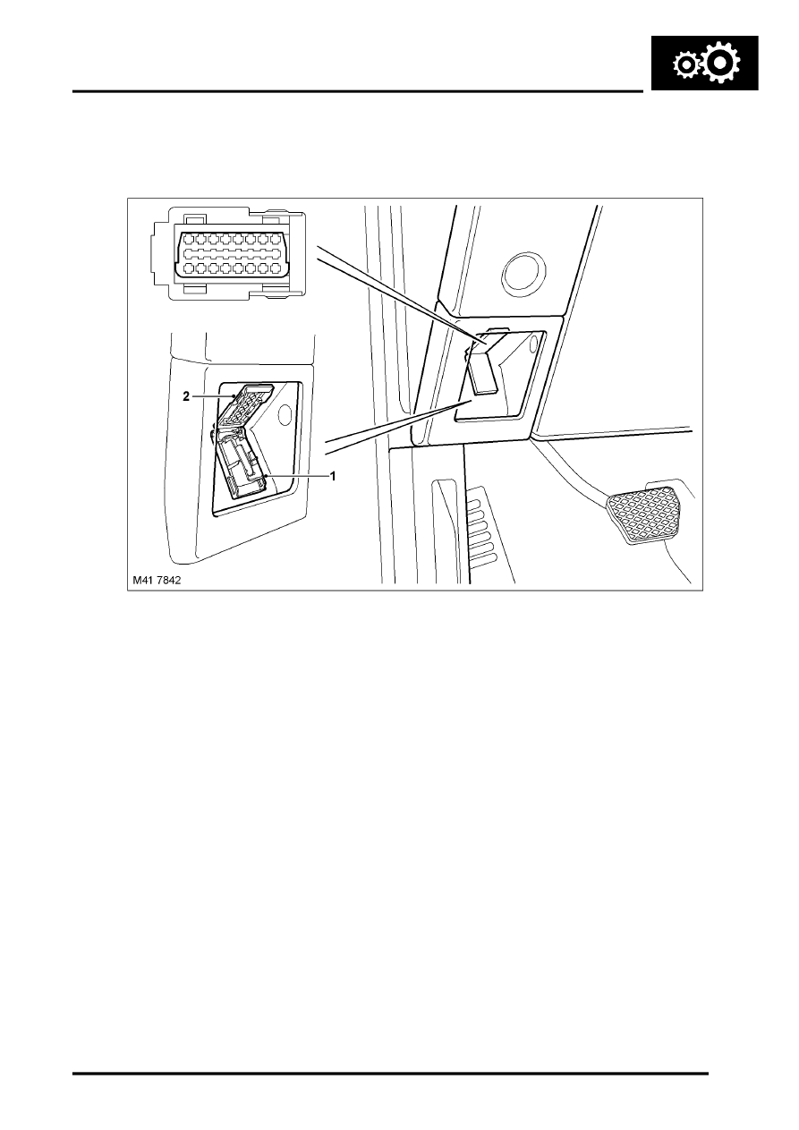
Diagnostic Socket
LHD model shown
1 Cover
2 Diagnostic socket
The information is communicated via a diagnostic socket which is located in the fascia, in the driver's side stowage
tray. The socket is secured in the fascia panel and protected by a hinged cover.
The diagnostic socket allows the exchange of information between the various ECU's on the bus systems and
TestBook/T4 or another suitable diagnostic tool. The information is communicated to the socket via a diagnostic DS2
bus. This allows the retrieval of diagnostic information and programming of certain functions using TestBook/T4 or
another suitable diagnostic tool.
The transfer box ECU uses Diagnostic Trouble Codes (DTC) which relate to transfer box electrical faults.
Controller Area Network (CAN) Bus
The CAN bus is a high speed broadcast network connected between various vehicle ECUs.
COMMUNICATION DATA BUSES, DESCRIPTION AND OPERATION, Description.
The CAN allows the fast exchange of data between ECU's every few microseconds. The bus comprises two wires
which are identified as CAN high (H) and CAN low (L). The two wires are coloured yellow/black (H) and yellow/brown
(L) and are twisted together to minimise electromagnetic interference (noise) produced by the CAN messages.
In the event of a CAN bus failure the following symptoms may be observed:
l
Shift from high to low or low to high inoperative
l
Instrument pack low range warning lamp inoperative
l
Instrument pack transfer box messages in message centre inoperative.