
L322 Range Rover System Description and Operation
AUTOMATIC TRANSMISSION – ZF 5HP24
DESCRIPTION AND OPERATION 44-2-35
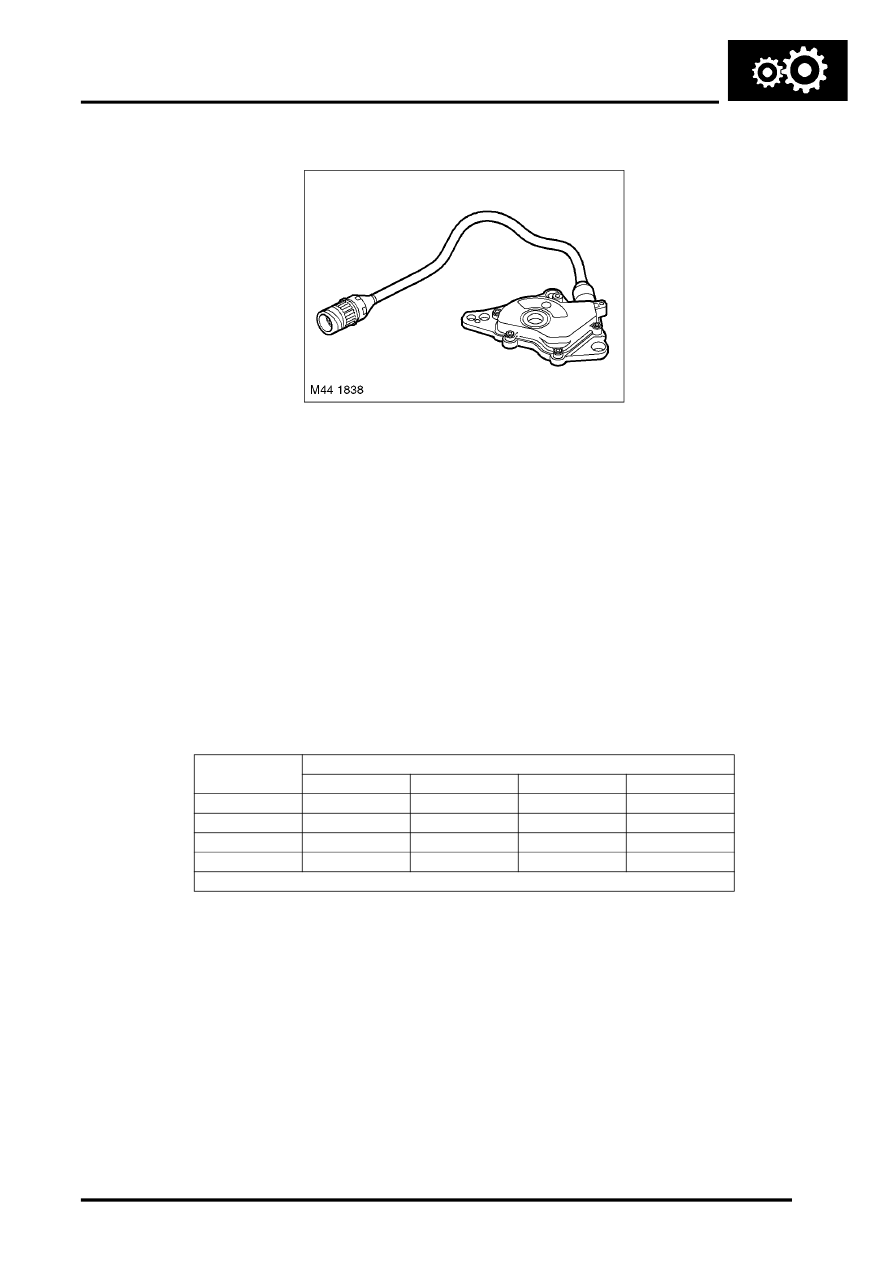
Inhibitor Switch
The inhibitor switch is located externally on the right hand side of the transmission. The switch is located on the
selector shaft and secured to the main casing with screws. A protective cover is also fitted over the switch to prevent
impact damage. The switch rotates with the selector shaft, moving the switch contacts to correspond to the selected
programme. The switch provides signals which allows the EAT ECU to monitor the position of the manual selector
spool valve and the selected drive programme.
The switch is connected via an integral harness and multiplug on five wires to the EAT ECU. One of the wires supplies
a 12V supply to the switch. The remaining wires are connected to the EAT ECU. When the transmission selector lever
is moved to the selected position, one or more of the contacts within the switch are made, completing a circuit back
to the ECU. From the switch contacts which are made, the ECU determines which selection is required and responds
accordingly.
When the selector lever is in Park, the EAT ECU transmits a signal to the immobilisation ECU to enable starter
operation. The signal also energises the starter relay, allowing the crank signal from the immobilisation ECU to pass
to the starter solenoid.
The following table shows which switch contacts are made for a given selector lever position.
Selector Lever
Position
Switch Contacts
L1
L2
L3
L4
Park
X
X
X
Reverse
X
X
Neutral
X
X
X
Drive
X
X = High signal