
L322 Range Rover System Description and Operation
SUSPENSION
60-28
DESCRIPTION AND OPERATION
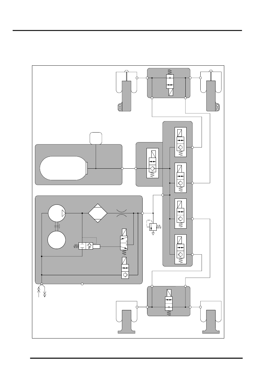
System Pneumatic Circuit
The following schematic diagram shows the connection relationship between the air supply unit, the reservoir, the
reservoir valve block, the cross-link valves and the air springs.
System Schematic Circuit Diagram
M60 0838A
1
2
3
4
9
10
11
14
18
19
15
16
20
M
5
6
7
8
12
13
21
22
17