
L322 Range Rover System Description and Operation
WIPERS AND WASHERS
84-18
DESCRIPTION AND OPERATION
Operation
Front Wipers
The front wiper system has the following functionality:
l
Intermittent wipe and delay adjustment
l
Normal (slow) speed wipe
l
Fast speed wipe
l
Programme wash/wipe
l
Flick wipe
l
Headlamp powerwash (if fitted)
l
Motor blocking protection.
Intermittent
Intermittent wiper operation is selected on the wiper control column switch, by moving the switch vertically, to the first
position. The intermittent delay period is adjustable using the rotary switch on the wiper control column switch. The
delay period is also subject to vehicle speed, with the selected delay period decreasing with an increase in road
speed.
The rotary potentiometer selects differing resistance values for each position. The potentiometer is connected into a
voltage divider circuit, with a 6.8k
Ω
resistor located in the BCU. The power supply to the voltage divider circuit is
limited to 6.5V. This reduced voltage is used by the BCU to determine the position of the rotary switch as follows:
The intermittent delay is also influenced by the road speed of the vehicle using a signal value derived from the ABS
ECU on the K bus. The delay periods for the vehicle stationary and when moving at different vehicle speeds are shown
in the following table:
The rotary switch positions also influence the operation of the rain sensor (when fitted) by adjusting its sensitivity.
Refer to the following Rain Sensor operation section for details.
Normal (Slow) Speed
The normal (slow) speed continuous wiper operation is selected by moving the switch vertically to the second detente
position. The wipers will operate continuously when the vehicle is moving. When the vehicle is stationary (less than
4 mph (6 km/h)), the BCU operates the wipers in the intermittent mode, using a 3 second intermittent delay period for
NAS and Australian market vehicles and a 5 second intermittent delay period for ROW vehicles.
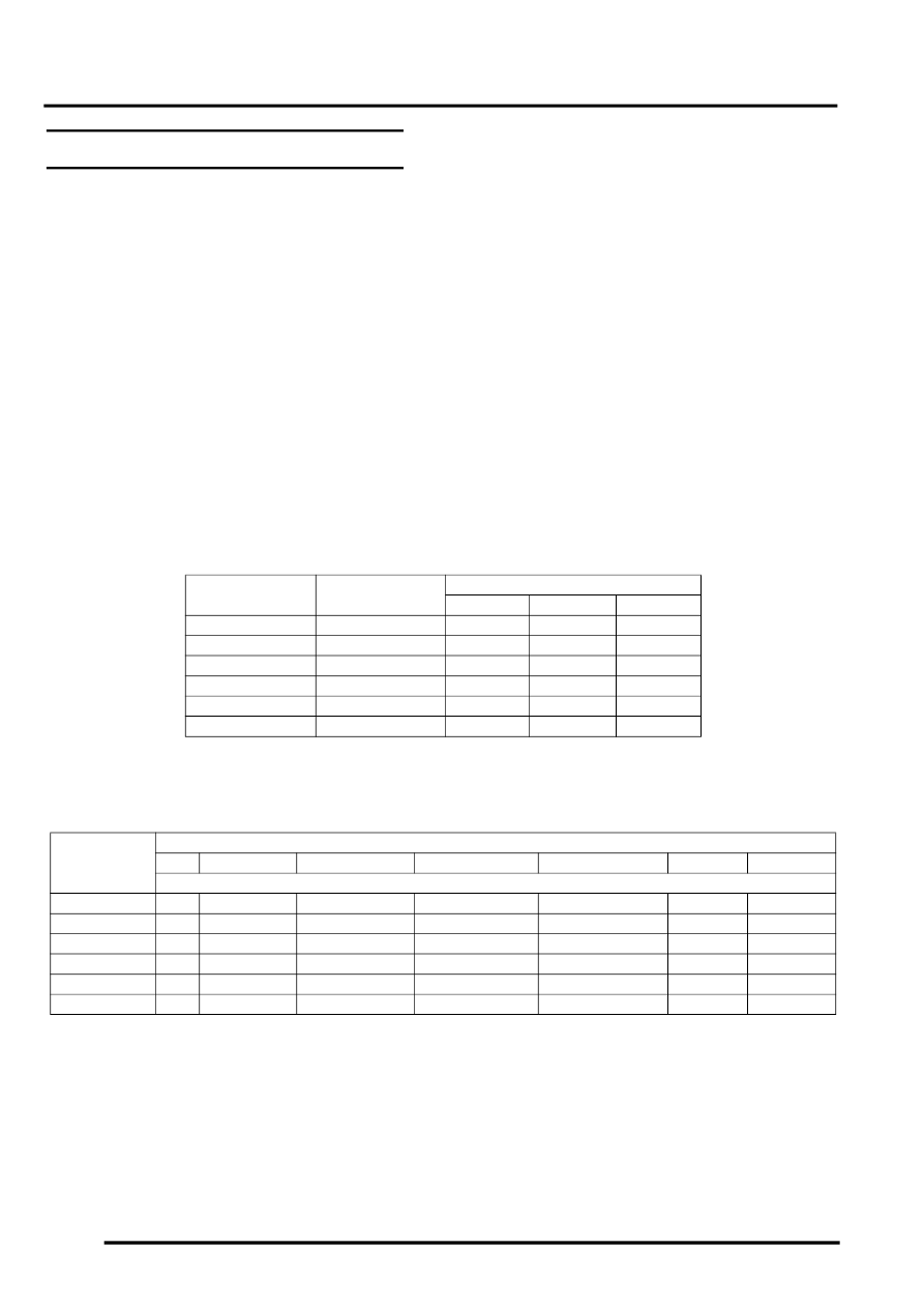
Rotary Switch
Position
Resistance
Voltage
Min
Max
Typical
Error - Ground
<0.2k
Ω
-
-
<0.18V
1
2k
Ω
±
750
Ω
1.00V
1.89V
1.48V
2
4k
Ω
±
750
Ω
2.08V
2.70V
2.41V
3
6k
Ω
±
750
Ω
2.80V
3.27V
3.04V
4
8k
Ω
±
750
Ω
3.32V
3.69V
3.51V
Error - Positive
>20k
Ω
-
-
4.88V
Rotary Switch
Position
Vehicle Speed mph (km/h)
4 (6)
4 - 19 (6 - 30)
19 - 44 (30 - 70)
44 - 62 (70 - 100)
62 - 87 (100 - 140)
>87 (140)
>112 (180)
Time Delay (seconds)
Error - Ground
20
6
5
4
3
3
3
1
26
19
17
15
15
13
13
2
17
12
11
10
9
7
7
3
10
6
6
5
4
3
3
4
5
3
3
2
2
2
2
Error - Positive
8
6
5
4
3
3
3