
L322 Range Rover System Description and Operation
LIGHTING
86-2-26 DESCRIPTION AND OPERATION
Instrument Panel and Switch Illumination Dimming
The LCM controls the instrument pack backlighting illumination and also illumination of all switches.
The LCM supplies a power output to all switch illumination bulbs at a voltage determined by the position of the manual
dimmer rheostat. The switch illumination is activated when the light control switch is in the side lamp or headlamp
position.
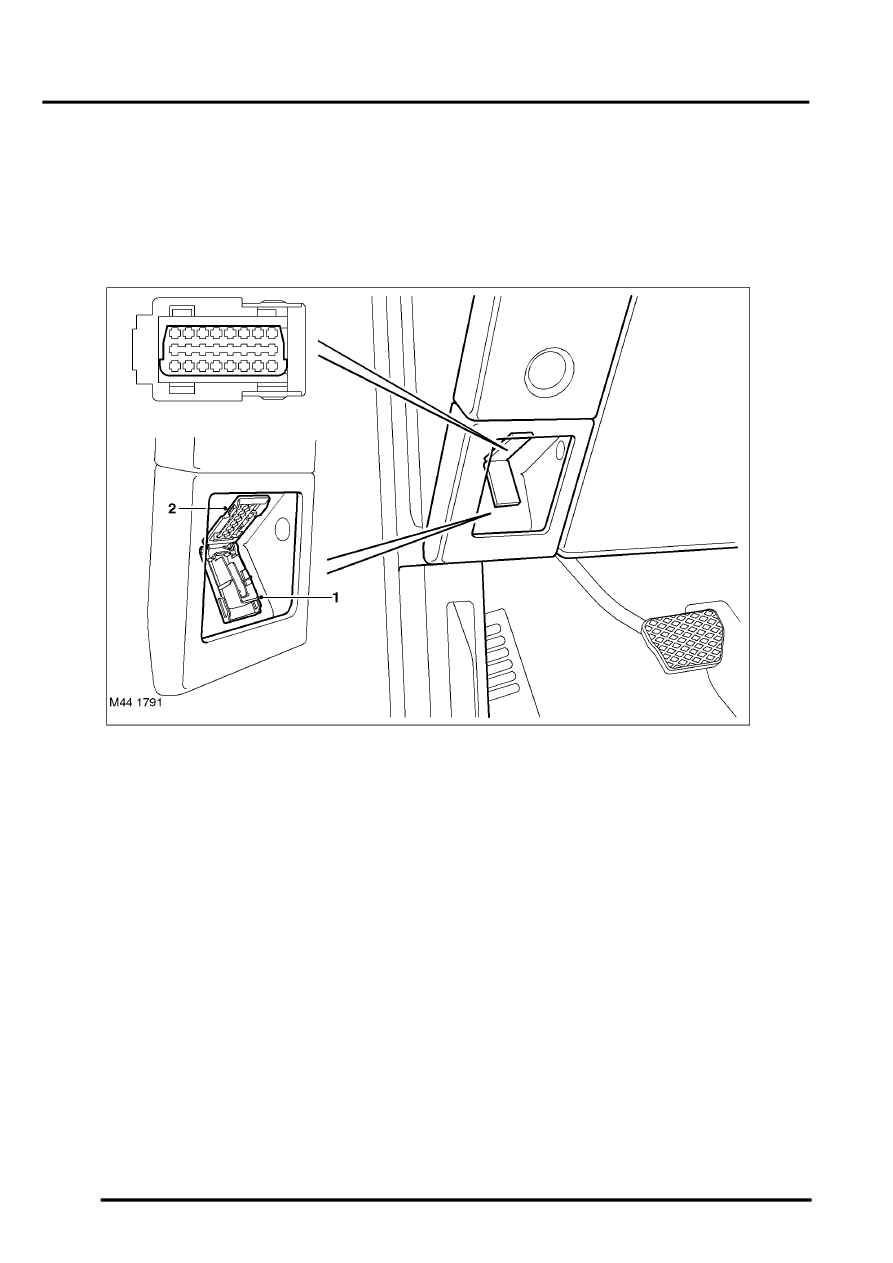
Diagnostics
1 Cover
2 Diagnostic socket
The diagnostic socket allows for the transfer of information between the LCM, the automatic headlamp levelling ECU
and TestBook/T4. The diagnostic socket is located in the fascia, in the driver's stowage tray. The socket is secured
in the fascia and protected by a hinged cover.
The LCM has diagnostic capabilities and store fault codes relating to the lighting systems. The xenon control modules
cannot be interrogated via the LCM, but the LCM incorporates xenon specific diagnosis up to the control modules.
The xenon control modules, located on the rear of the headlamp assemblies, can be interrogated using TestBook/T4
for faults relating to the operation of the xenon lamps. The control modules are connected on a DS2 link to the
diagnostic socket.